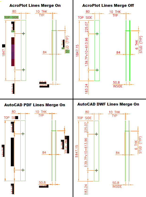
There is a bug in the newer versions of AutoCAD (2011 and 2012 for sure) related to the combination of Textmasks and using Lines Merge. It happens to all printer drivers (that support lines merge) when you enable lines merge support in the Pc3 file.
Please note that this is very random that it does happen but we have not been able to determine what in a particular file causes AutoCAD to render the output wrong.

As you can see the same file can vary depending on which print output AutoCAD uses (PDF, DWF, Windows System Driver) but they all have problems when lines merge is enabled on some legacy drawings.
Sometimes it will completely cover the text, other times it might only cover part of it, and still other times it might just be small lines as seen in the DWF example on this file.
If you don't believe us try creating a DWF file with lines merge enabled and you will likely get weird colored or black backgrounds in your textmask and the DWF output is a direct conversion from AutoCAD to file which bypasses the Windows System printing. This to me say the problem lies solely in Autodesk's own code rendering the textmasks, not on our side or windows side of things.
In our testing we tested the following output all of which displayed the problem when lines merge was turned on.
-
Our PDF-XChange for AcroPlot Pro driver.
-
Autodesk's own DWF6 driver.
-
Autodesk's own DWG To PDF driver.
-
Microsoft XPS Document Writer
-
HP Photoshop Premium Inkjet Desktop Printer.
What we have found out so far is.
-
It appears to only happen with legacy drawings or drawings that have had legacy blocks inserted. We have not been able to reproduce the problem when creating a new drawing with Mtext masks and multileader masks.
-
It only happens if you enable lines merge in the Pc3 configuration. Hence this is why it does not happen when going to Postscript based drivers because they do not support lines merge.
-
It happens to MText and Multileader backgrounds.
-
It's related to the background mask. Select all MText and Multileaders in the drawing and turn the Background Mask off and your output will be fine also. Try selecting one of the problem ones and increase it's background mask to 5.0 when you have it turned on and you will see a larger box.
-
In our testing it seams like the background masks set to the drawing background tend to turn out green where colored backgrounds will tend to be partially colored and partially black. Although at times some masks end up being multiple colors.
-
We have tested both with ctb files and without them and it happens both ways.
-
Since it doesn't appear to be a problem in 2010 and prior versions and since 2011 I believe is when they implemented per object transparency I would have to say that they screwed something up when they added that feature in. But that's just my opinion.
-
In my opinion Autodesk has never correctly implemented the whole black/white/background since they allowed you to change the background color. But it looks like we are stuck with it for another 20 years.
If you are a large enough customer and have some pull with your Reseller maybe they can get AutoCAD to fix their bugs. We have reported it but unfortunately it's not a developer problem so we have no pull with the rest of Autodesk. Also it's our experience in the past that they seldom fix what is wrong in the plotting routines, just introduce more bugs. It took them probably 5 or more releases to finally fix the Mtext background masks becoming transparent when you enabled lines merge but now we have even bigger problems with it.

